
New Quadruped Platform
Knee Joint Actuation Method
Considered direct drive (e.g. ANYmal), 4-bar linkage (e.g. PADWQ), chain drive (e.g. MIT Cheetah), and belt drive (e.g. MIT mini cheetah) mechanisms
Ended up going with a belt drive for its simplicity, weight characteristics, and ability to repair and/or change gear ratios later on in the design process
-
Direct Drive had great potential for a high torque control bandwidth, but did not fit our desire for an easily modifiable knee joint design with respect to gearing ratio. This design also placed a large amount of mass far from the center of mass increasing the leg inertia.
-
4-Bar Linkage had great potential for high torque and control bandwidth, but greatly reduces the adjustability of parameters such as knee joint mechanical advantage and repairability.
-
Chain drive actuation lowered the available torque control bandwidth but provided a robust, easy to adjust, and easy to repair knee design.
-
Belt drive actuation method encapsulated all the positives of the chain drive actuation method with the added bonus of being lighter and having lower maintenance requirements.

Initial Leg Design Research & Concept
Actuator Configuration
3 actuator configurations were analyzed to determine the optimal configuration for this project.
The first design was the state of the art abduction/adduction actuator mounted first with the hip actuator followed by the knee motor. This configuration is great for efficiency in walking and standing gaits but reduces the ability for forward manipulation with the front limbs.
The second design started with the hip actuator mounted to the body followed by the ab/ad actuator and then the knee actuator. This design greatly improved forward manipulability but with the added effect of increasing the inertia around the base joint and increasing the complexity of the actuator mount designs required.
The third and final design considered mounted the ab/ad actuator at the base similar to the first design but then mounted the hip and knee actuators in parallel in order to improve the speed and power output at the legs. This design came with the caveat of mechanical antagonism increasing the amount of power required to complete simple gaits such as walking.
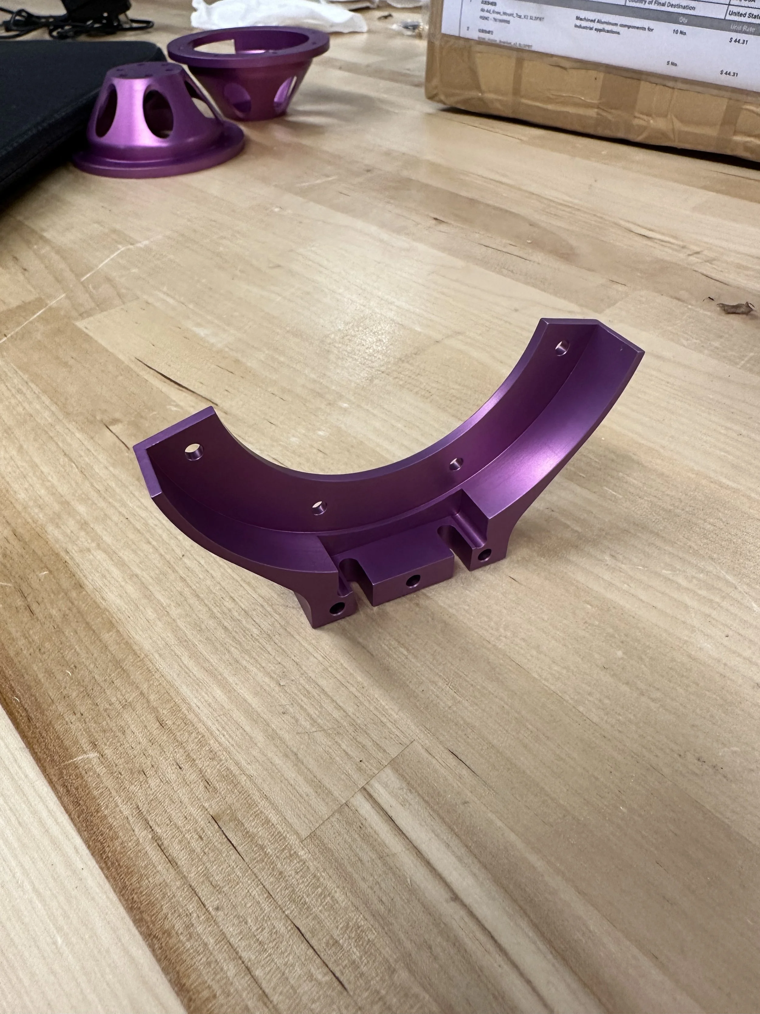
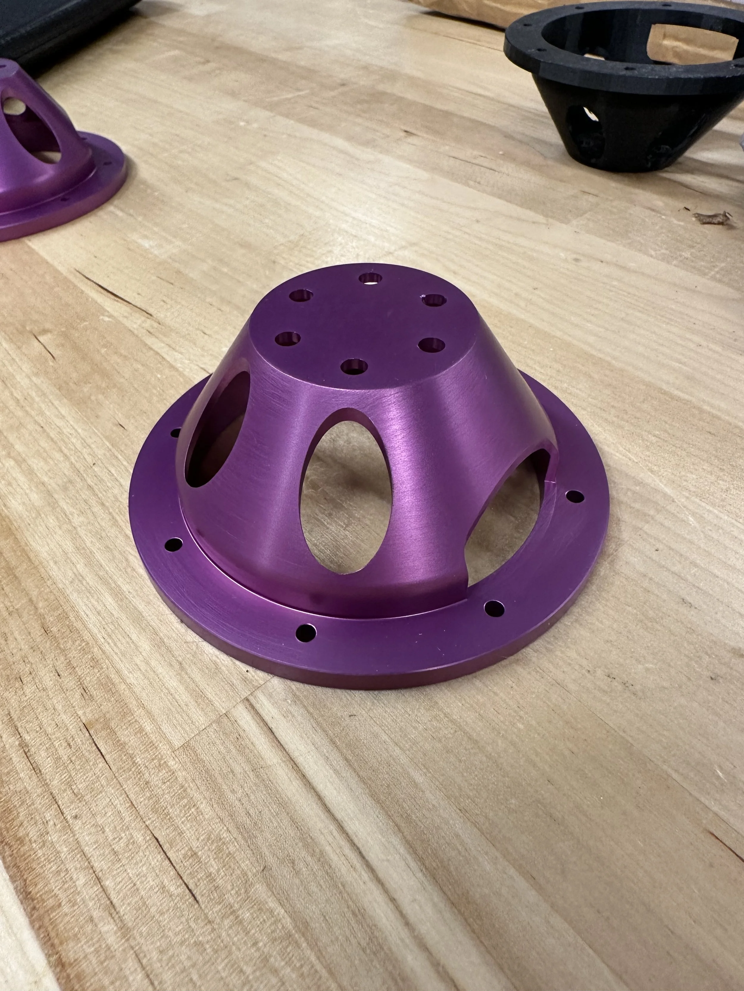
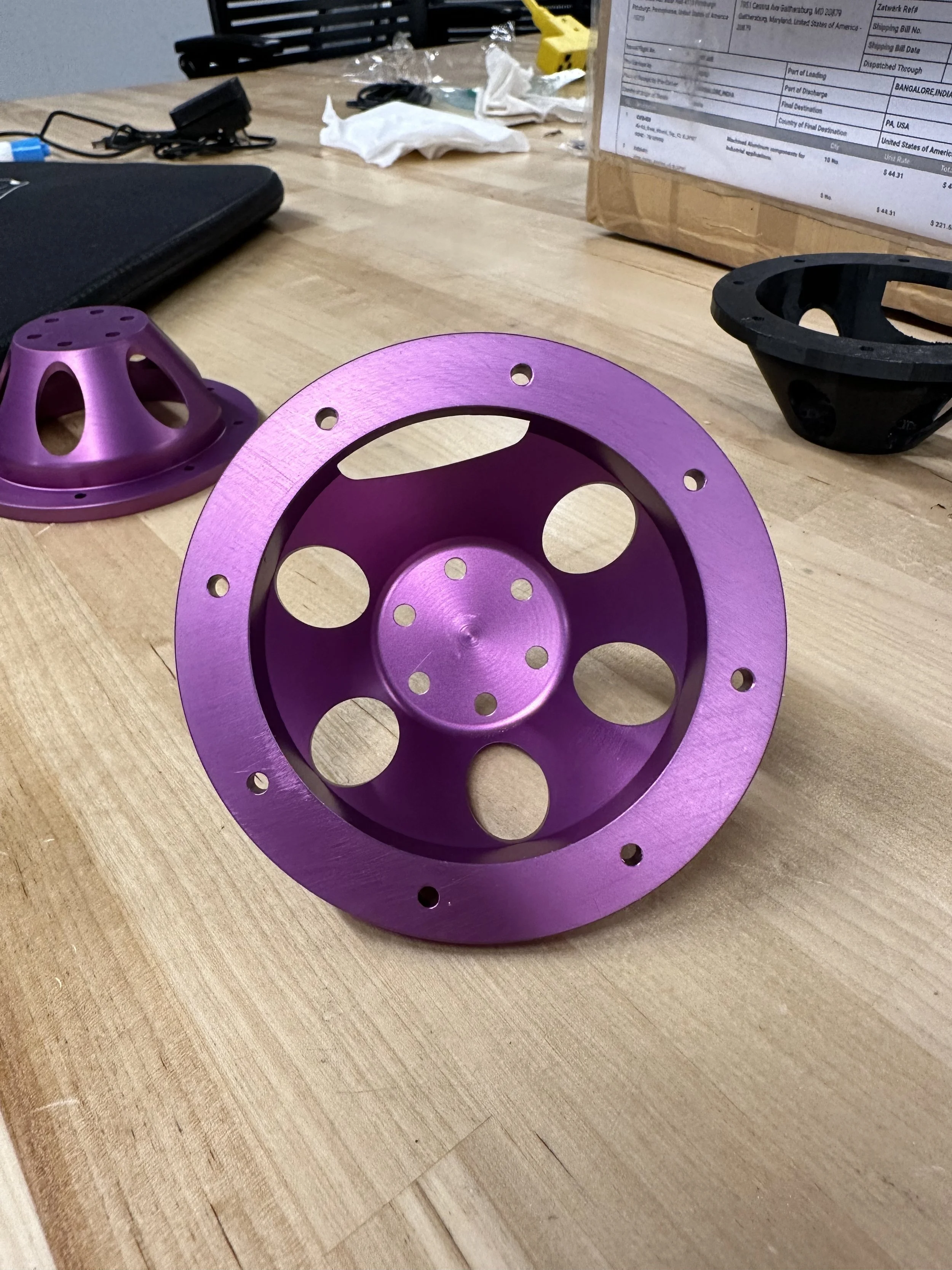
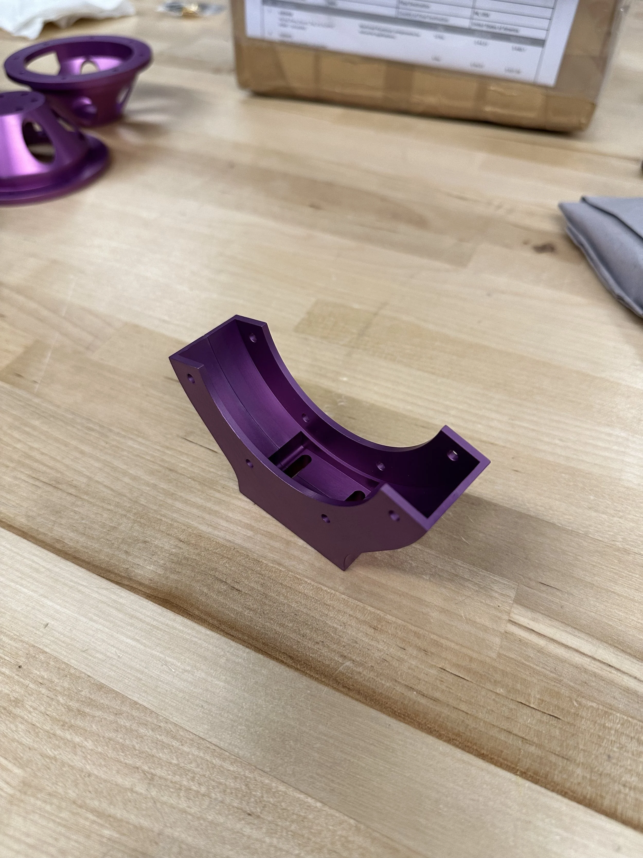
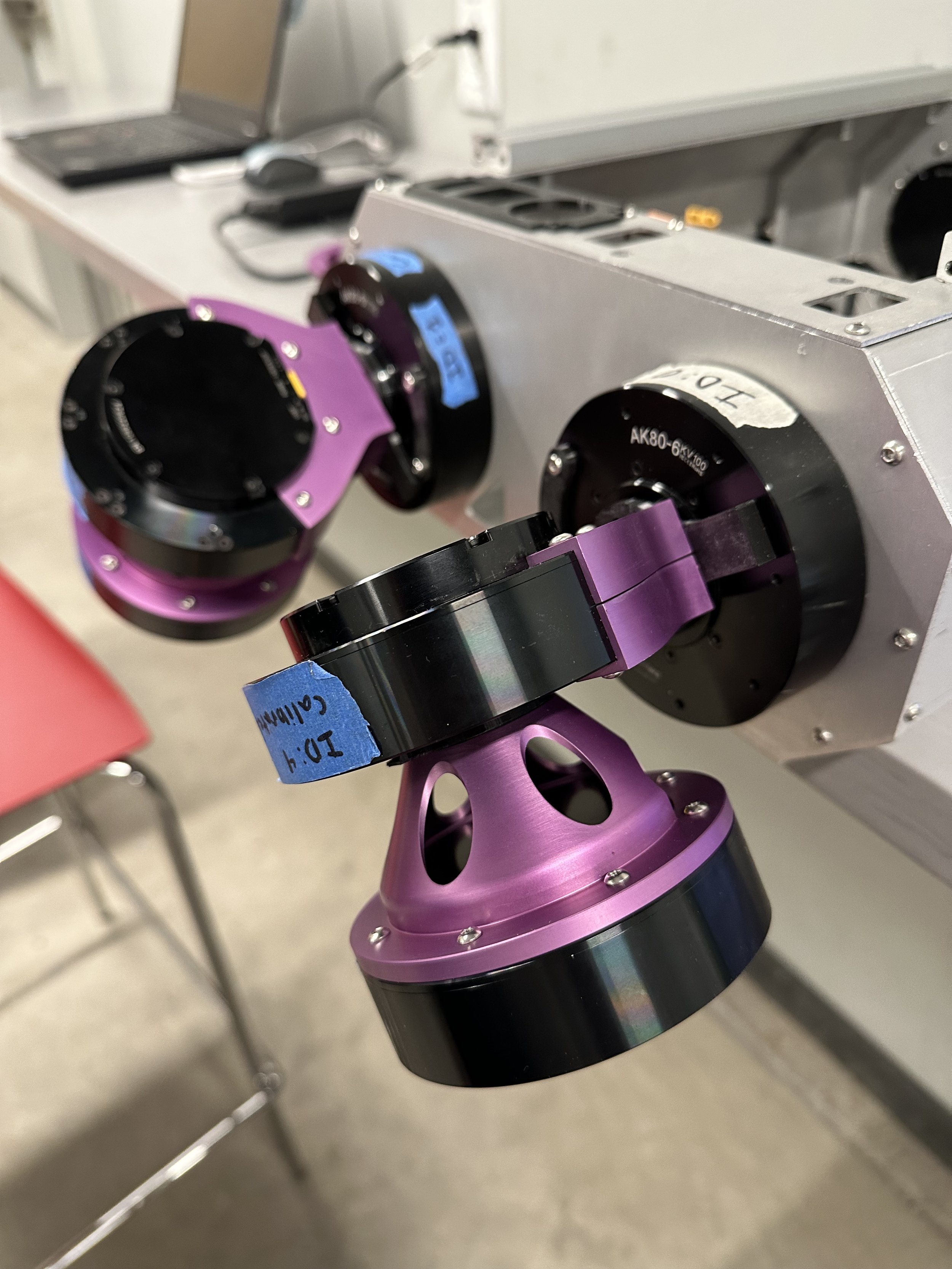
Upon considering the pros and cons of all 3 designs, the state of the art (design 1) was chosen for our specific application shown above in the initial concept design. Shown below are CAD and final manufactured product images of the actuator mounts I designed.
Undergraduate Researcher Role
Electronics Design & Integration
Using AK80-6 V2 motors for all 12 joints
CAN bus for communication to each motor
Separate CAN busses for front and rear legs to improve speed of communication
Powered by 2 14.8V LiPo batteries in series to supply ~29V to the whole robot
Voltage step down regulator used to convert the 29V supply line to 19V for use by the onboard NUC
Graduate Researcher Role
Software Design & Integration
Onboard Intel NUC Canyon Phantom running Ubuntu 20.04 with ROS noetic
New Platform Interface class interfaces with the Robomechanics lab quad-sdk software to recieve leg command messages and convert them into CAN messages for each motor using the mini-cheetah-can library for C++
To conduct tests on the interface, we used an oscilloscope to catch the CAN messages as they were sent to the motors without powering the motors. This was done to test the communication pathways from the ROS nodes to the motors without needing to have an e-stop ready to go.
Motor communication pipeline testing with prototype leg attached.
First successful stand test